2/SETTING UP THE MC-10
Proper connection of the MC-10 to a TV, a power source, and various optional equipment is important if your Computer is to provide you with reliable service.
Place the Computer on a solid surface near the TV set you'll be using. An appropriate power source should be nearby. We do not recommend using a regular extension cord if a power source is not close enough for direct connection. Instead, try using Radio Shack's Plug-In Power Strip (Radio Shack Catalog Number 61-2619) or the Power Line Filter (26-1451).
Do not connect the computer to the AC power source yet.
Connection to a TV
The MC-10 contains its own, built-in television interface which converts information the computer understands to information the television understands. That information is then sent as a VHF signal to your TV.
Note that the MC-10 comes with an Antenna Switchbox. This Switchbox enables you to use your TV for normal viewing or for computer operation without having to connect/disconnect the computer everytime you use it. Set the Switchbox's slide-switch to:
- TV, for normal television viewing.
- COMPUTER, for computer input.
Mounting the Antenna Switchbox
The Switchbox consists of a:
- Box
- Short section of twin-lead cable (like the cable which connects an antenna to your TV)
- Two screw terminals
- Coaxial connector
- Slide switch
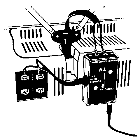
We suggest you attach the Switchbox to the back of your TV. See Figure 6.
To mount the Switchbox, follow these steps:
1. Select a smooth, flat surface on the TV that is well within reach of the antenna cables. Wipe off any dust, dirt, or grease from the mounting surface.
2. Remove the backing from the double-sided tape (one side is already attached to the Switchbox) to expose the sticky surface.
3. Press it against the back of the TV in the desired location.
Connecting the Antenna Cable to the Switchbox
You need to connect the VHF antenna cables (that come from an external antenna or the TV's internal antenna) to the Switchbox. If these wires are presently connected to the VHF terminals on your TV set, disconnect them now. (Be sure to use a small screwdriver.)
What you do next depends on the type of antenna installation you have. Read the following section and pay careful attention to Figures 7 through 12 to decide which installation you have.
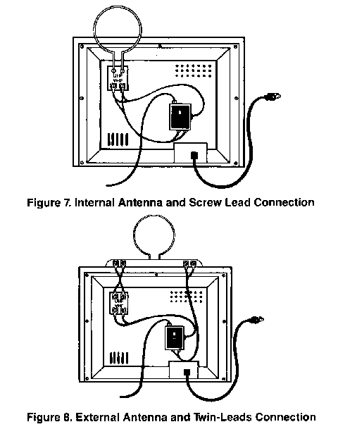
Internal Antenna and Screw Leads Connect the internal antenna cables from the TV to the terminals on the Switchbox labeled CONNECT TO ANTENNA. Then connect the short twin-lead cable from the Antenna Switchbox to your TV's VHF screw terminals. See Figure 7.
External Antenna and Twin-Leads Connect the cable from the external antenna (including Rabbit Ears) to the terminals on the Antenna Switchbox labeled CONNECT TO ANTENNA. Connect the short twin-lead from the Antenna Switchbox to your TV's VHF screw terminals. See Figure 8.
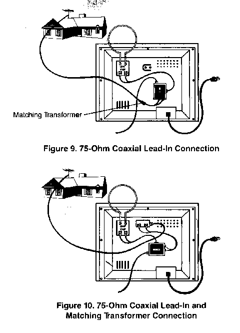
75-Ohm Coaxial Lead-In To make this connection, you will need to obtain a special 75-ohm to 300-ohm matching transformer. We suggest Radio Shack's Indoor/Outdoor Matching Transformer (15-1140). Connect your coaxial cable lead-in to the transformer and connect the transformer's twin-lead to the screw terminals on the Antenna Switchbox.
Move the TV's slide switch to the CLOSED position.
Connect the short twin-lead from the Antenna Switchbox to your TV's VHF screw terminals. See Figure 9.
75-Ohm Coaxial Lead-In and Matching Transformer Connect the short twin-leads from the transformers to the screw terminals on the Antenna Switchbox. Connect the short twin-leads from the Antenna Switchbox to your TV's VHF screw terminals. See Figure 10.
In this section, we have shown five typical TV antenna installations. There are some other antenna types and features you may need to be aware of, however.
- If your TV has a 75-300-ohm switch on the back, be sure the switch is set to the 300-ohm position.
- If your TV has a round jumper cable protruding from the back, be sure the jumper cable has been attached to the connector next to it.
- If your TV's antenna system is one we've just described, there should be no problem at all. The connections between the other TV antenna terminals and the Antenna Switchbox will be as in one of the illustrations.
- If you have cable TV, we strongly recommend that you call in a qualified service technician.
Connecting the MC-10 to the Switchbox
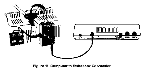
After connecting your TV's antenna to the Antenna Switchbox, connect the Computer's coaxial cable (supplied with the MC-10 package) to the Computer's TO TV connector on one end and the Antenna Switchbox's COMPUTER connector on the other. Note that both ends of the cable are the same. See Figure 11.
Your MC-10 Computer is now ready for use.
Connection to a Cassette Recorder
To save programs or data for future use, you'll want to store information on cassette tape. We suggest you use Radio Shack's CCR-81 Computer Recorder (26-1208) and our C-20 Leaderless Computer Cassette Tapes (26-301). If you use a different recorder, connection and operation may vary.
Note: You do not need to connect the Cassette Recorder unless you plan to record programs, save data, or load previously taped programs into the MC-10.
The CCR-81 cassette recorder includes a cable specifically designed for computer's such as the MC-10. We recommend you use this cable only.
1. Connect the short cable (DIN plug on one end and three plugs on the other) to the CASSETTE connector on the back of the Computer. Be sure you get the plug to mate correctly.
The three plugs on the other end of the cable are for connection to the recorder.
2. Connect the black plug into the EAR jack on the side of the recorder.
This connection provides the output signal from the recorder to the MC-10 (for loading tape programs into the Computer).
3. Connect the larger gray plug into the AUX jack on the side of the recorder. This connection provides the recording signal to record programs from the Computer onto the tape.
Leave the AUX plug in whether you are recording or playing back cassette data.
4. Connect the smaller gray plug into the smaller MIC jack on the recorder.
Note: Do not plug a remote microphone or a dummy plug into the larger MIC jack.
Connection to a Printer
Radio Shack provides a thermal printer, the TP-10 (26-1261) which is specifically designed for the MC-10. This printer provides a 32-column print out on 4" wide paper and is capable of printing all the graphics the MC-10 can produce.
However, you can use any Radio Shack serial printer or plotter with the MC-10. This includes the:
- Line Printer VII (26-1167)
- Line Printer VIII (26-1168)
- DMP-100 (26-1253)
- DMP-120 (26-1255)
- DMP-200 (26-1254)
- DMP-400 (26-1251)
- CGP-115 Plotter/Printer (26-1192)
- FP-215 Flatbed Plotter (26-1193)
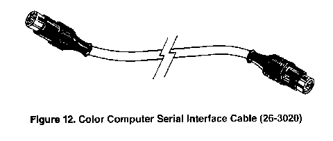
To use the MC-10 with any of these printers or plotters, you'll need to use the proper connecting cable. To connect the MC-10 to any of these optional devices, you'll need the Color Computer Serial Interface Cable (see Figure 12).
Before connecting any accessory device (such as a serial printer) to the MC-10, be sure that both the Computer and the accessory are both turned OFF.
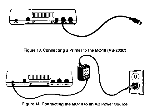
To connect a printer to the MC-10:
1. Insert one end of the Color Computer Serial Cable into the RS-232C Connector on the Computer.
2. Connect the other end of the Cable to the SERIAL I/O CONNECTOR (4-pin DIN jack) on the Connection Panel of the printer or plotter.
Note that the MC-10 has full, RS232C communications capabilities. This means that the RS232C Connector can be used with any RS232C compatible device, including modems. A modem will allow you to transmit information over the telephone to other computers via the RS232C Connector as long as you have communications software.
Connection to a Power Source
Before connecting the MC-10 to a power source, be sure all accessories (such as printer or recorder) are turned OFF!
The MC-10 comes with an AC adapter. Do not use any other AC Adapter or you may damage your Computer!
Try to have the MC-10 close to a 120V AC wall-outlet. If it is not close enough, we suggest that you use an approved power strip, such as the Radio Shack Plug-In Power Strip (61-2619) or the Power Line Filter (26-1451) instead of a lightweight extension cord.
Power requirements for Radio Shack products are specified on the unit or in the "Specifications" section of the appropriate owner's manual.
Note the AC Adapter has two cords exiting it-one that has a round plug on the end and another that has a flat plug.
To connect the MC-10 to a power source:
1. Insert the round plug into the AC ADAPTER Connector on the back of the MC-10.
2. Insert the flat plug into the AC power source.
|
|